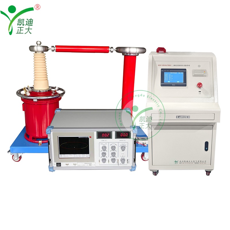
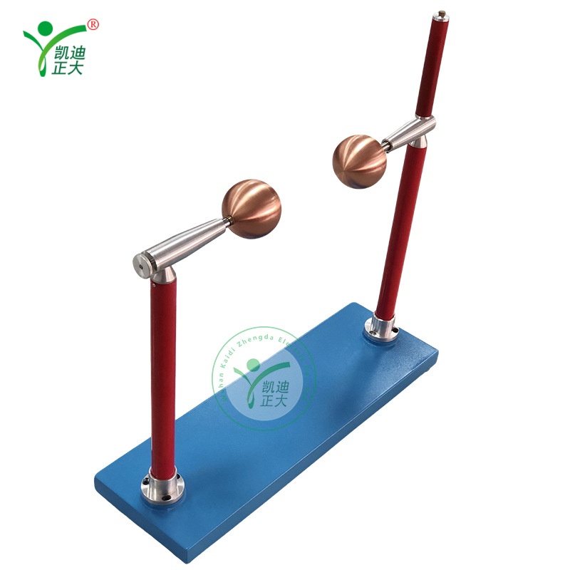
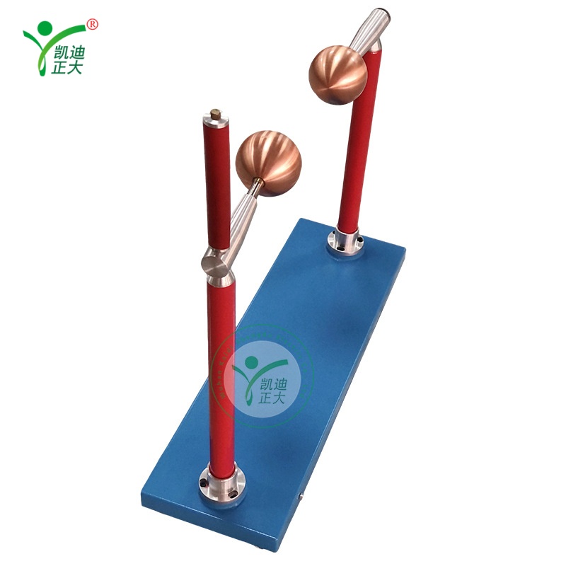
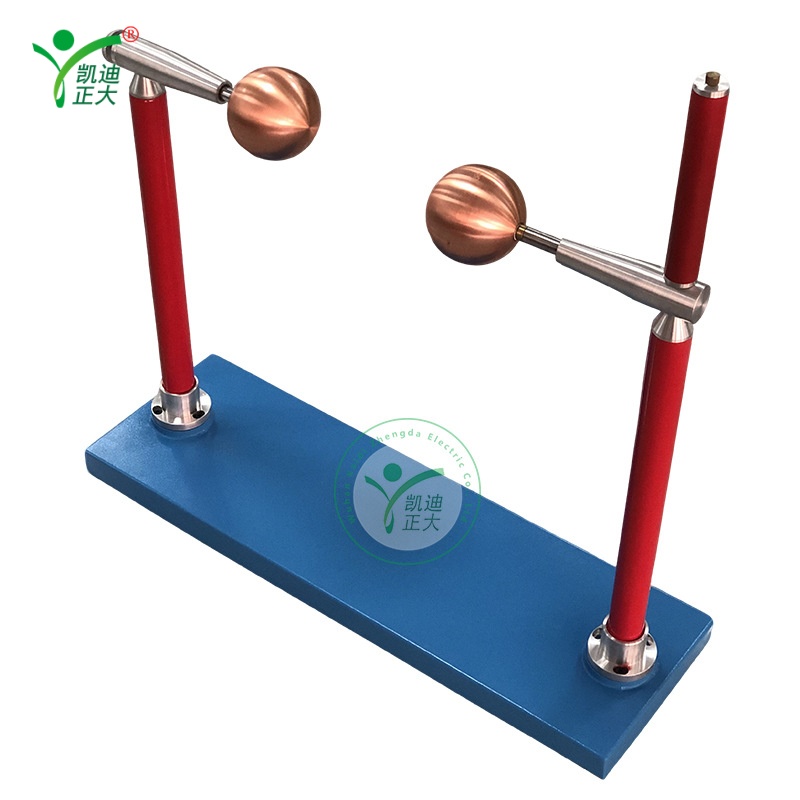
When conducting the experiment, connect the ball gap device in parallel with the test sample. The ball gap device itself has a protective resistor of 1 ohm per volt in series. First, adjust the ball gap to 60% of the test voltage (the discharge distance of the ball gap can be checked from the ball gap discharge voltmeter below, Tables 1 and 2). At this time, the test sample should be connected simultaneously. Measure the readings of the test transformer and low-voltage side voltmeter when the ball gap is discharged (take the average of 3-4 times), and then measure the readings of the voltmeter at 70% and 80% of the test voltage in the same way. Use this three-point line value as a curve (mostly a straight line), and then extend this curve (mostly calculated proportionally) to a position 10-15% higher than the required test voltage, as a discharge protection against overvoltage that may occur during the withstand voltage test process.
Response within
24 hours
Free warranty
12 month
On-line training
Support