Profile:
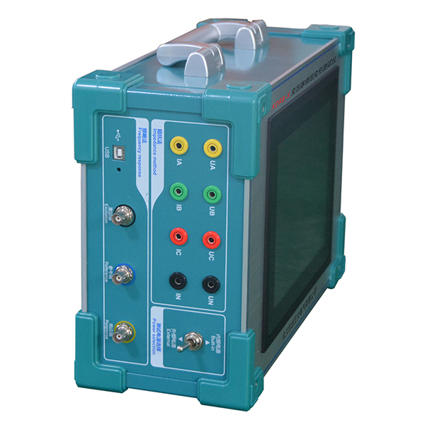
KDRB-X integrates FRA and impedance methods into a high-precision measurement system with built-in industrial computer or laptop connectivity. It employs DDS digital scanning technology and high-speed dual-channel 16-bit A/D sampling for accurate winding fault diagnosis. The device automatically analyzes results and generates Word documents, conforming to DL/T911-2016 and DL/T1093-2008 standards, enabling comprehensive integrity assessment of transformers.
Features:
1. High-speed, highly integrated data acquisition and control ensures reliable performance;
2. Operates independently on an industrial computer or via USB connection to a laptop, facilitating flexible on-site use;
3. Automatically analyzes and judges test results, generating Word documents for saving and printing;
4. Complies with DL/T911-2016 (France) and DL/T1093-2008 (Reactance Method) standards;
5. Dual high-speed 16-bit A/D sampling, capturing clear waveform changes via tap switching;
6. DDS dedicated digital high-speed sweep frequency technology (USA) accurately diagnoses distortion, bulging, displacement, tilting, inter-turn short circuits, and phase-to-phase contact short circuits;
7. Dual measurement systems: linear sweep frequency and segmented sweep frequency, compatible with two domestic technical solutions;
8. Customizable curve printing with arbitrary linear or logarithmic scale on the amplitude-frequency characteristic horizontal axis;
9. Impedance method uses a short-circuit connection for single-phase measurement: instantaneous high-voltage side connection, automatically calculating the short-circuit impedance of each phase;
10. Simultaneously measures voltage, current, and frequency with real-time waveform display;
11. Dual power supply option: built-in 220V or external power supply for impedance testing.
Parameter:
Frequency response method:
Scanning method
1. Linear scanning distribution
Sweep frequency measurement range: (10Hz) - (10MHz) 40000 sweep frequency points, with resolutions of 0.25kHz, 0.5kHz, and 1kHz.
2. Segmented sweep frequency measurement distribution
Sweep frequency measurement range: (0.5kHz) - (1MHz), 2000 sweep frequency points;
(0.5kHz)-(10kHz)
(10kHz)-(100kHz)
(100kHz)-(500kHz)
(500kHz)-(1000kHz)
Other technical parameters
Range of amplitude measurement: (-120dB) to (+20dB)
Amplitude measurement accuracy: 0.1dB
Scanning frequency accuracy: 0.01%
Signal input impedance: 1M Ω
Signal output impedance: 50 Ω
Signal output amplitude: ± 20V
Same phase test repetition rate: 99.9%
Impedance method:
Measurement accuracy: Voltage: 0.2% Current: 0.2%
Impedance range: 0-100%
Voltage measurement range: AC 25V~500V
Current measurement range: AC 0.1A~10A
Working humidity: 0-80%
Same phase test repetition rate: 99.9%

")