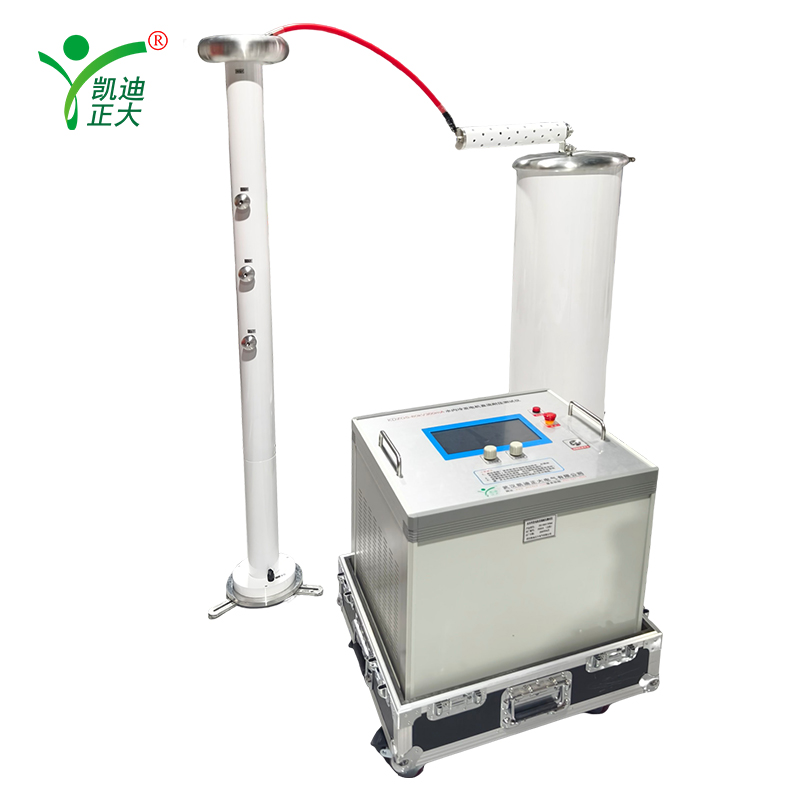
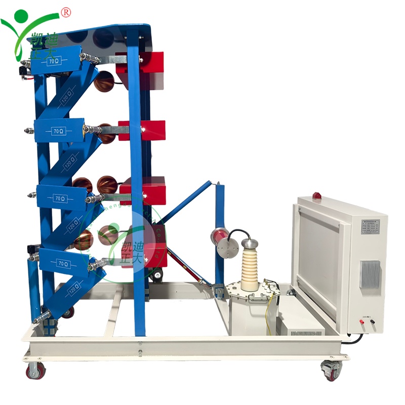
Products

Products

KDCJ-400kV/20kJ automatic impulse voltage generator

KDCJ-400kV/20kJ automatic impulse voltage generator

Applications:

This parameter is applicable to the full wave test equipment of lightning impulse voltage of transformers, transformers, switches and other power products such as 35kV and below.

  • Response within
    24 hours

  • Free warranty
    12 month

  • On-line training
    Support

Profile:

2. Reference the execution standard
GB311.1 Insulation coordination of high voltage power transmission and transformation equipment
GB/T16927.1 High voltage test technology General test requirements
GB/T16927.2 High voltage test technology measurement system
GB/T16896.1 Digital recorder for high voltage shock test
ZB F24001-90 Implementation Rules for impulse voltage measurement
GB191 packing mark
GB4208 enclosure protection class
GB813-89 shock test oscilloscope and peak meter

Features:

3. Conditions of use
The impulse voltage generator test system is mainly applicable to the impact of high voltage equipment of 35kV and below
Full wave test can also be used for impact test of other products.
3.1 The altitude shall not exceed 1500m
3.2 Ambient temperature: -15~+50℃
3.3 Air relative humidity: ≤90%
3.4 Installation location: indoor use, movable
3.5 There must be a reliable ground point with a ground resistance ≤0.5Ω

Parameter:

4. Impact generator (Model: KDCJ-400/20)
4.1 Main technical parameters of impact generator
4.1.1 Nominal lightning wave impulse voltage: 400kV
4.1.2 Nominal capacity (energy) : 20kJ
4.1.3 Capacitance: 1.0μF,100kV dry fully insulated package
4.1.4 Level voltage: 100kV
4.1.5 Stage/stage capacity: 4/5kJ
4.1.6 Output waveform: 1.2μs/±30%/50μs±20% standard lightning impulse voltage full wave
4.1.7 Synchronization Range: Greater than 20%
4.1.8 Use duration:
It can work continuously when the rated operating voltage is less than 80%
It can work intermittently when the rated working voltage is greater than 80%
4.1.9 Amplitude adjustment error voltage difference is less than 1%, and the minimum output voltage is less than 10% of the device nominal voltage.
4.1.10 Synchronization error Rate: Less than 1%
 
4.2 Technical description of impulse voltage generator
4.2.1 Structure of the generator
4.2.1.1 The main loop design of SGS series of HAEFELY Company in Switzerland is adopted, so as to realize the overall ultra-small size.
4.2.1.2 Using ball trigger, error-free trigger, small wear, and fast and accurate positioning.
4.2.1.3 The fixed mechanism of modulating resistance with spring crimping and easy insertion ensures the reliability of contact and makes the output waveform smooth without burrs.
4.2.1.4 By ball trigger can make synchronous ball gap with more than 20% trigger range, to ensure the reliability of triggering, automatic control is convenient and reliable.
4.2.1.5 The trigger of synchronous ball gap has no polarity effect and does not require bilateral trigger.
 
4.2.2 Main capacitor
4.2.2.1 The main capacitor adopts high-density solid capacitor, the DC working voltage of each capacitor is ±100kV, the inherent inductance of the capacitor is small, light weight and small volume, which is the first in China.
4.2.2.2 The concave and convex deformation of the capacitor is less than 1mm in the normal working state and working environment.
4.2.2.3 The capacitor is a solid insulating medium and the shell is dry and fully insulated package, and there are no problems such as oil leakage and deformation.
 
4.2.3 Modulating element
4.2.3.1 The wave head and wave tail resistors have sufficient heat capacity, which can ensure the generator to run continuously for a long time.
4.2.3.2 The charging resistor has sufficient heat capacity to ensure the generator to run continuously for a long time.
4.2.3.3 Wave head and wave tail resistors are made of plate structure, non-inductive winding of Constantine wire, vacuum casting of insulating resin, spring crimping joint, easy to install.
4.2.3.4 Connecting heads of wave head and wave tail resistors are made of 3mm stainless steel wire-cut.
4.2.3.5 It is equipped with a wave head resistance and a wave tail resistance for lightning shock wave modulation, and a group of charging resistance and protection resistance.
 
4.2.4 Control and protect the system
4.2.4.1 The IGCS-2020 automatic control system is adopted to provide various controls for the main part of the impulse voltage generator and meet the various control functions of the impulse test. The IGCS-2020 control system uses imported components, and the connection with the main body of the equipment uses two fiber cables.
The IGCS-2020 automatic control system takes the programmable controller as the core device, so the volume of the controller is very small, and the controller can realize manual control and automatic control. The use of special software packages can be controlled by computer, so as to achieve intelligent operation. The special software package can be used with the digital acquisition card for measurement and waveform analysis to realize the integration of computer measurement and control of impulse voltage test system.
 
4.2.4.2 The control system has the following control functions:
PLC technology is used to transmit control commands and feedback equipment status using two-core optical fiber, thus avoiding electromagnetic interference and improving the security of control system and computer.
The control function has manual, automatic and program control functions, and each level of function is relatively independent to ensure the reliability of the system.
Using thyristor voltage regulation mode, with charging voltage feedback measurement system.
The ignition gap can be adjusted manually and automatically, and is displayed on the LCD panel.
The stability of charging voltage can reach 0.5% by using constant current charging mode controlled by function.
The LCD panel can indicate the charging voltage and charging process of the shock generator with an accuracy of 1%.
The charging voltage and charging time can be directly input from the LCD panel.
With charging abnormal protection function, automatic or manual trigger ignition pulse
Indication of the working state of the impact generator, such as self-discharge, no trigger, normal trigger, etc.
Grounding and grounding release control of the main body and charging part of the device.
The charging process of the charging voltage can be controlled automatically or manually
The alarm can be automatically or manually sounded
With over current and over voltage automatic protection
Isolation filter shield design
 
4.2.5 Grounding System
4.2.5.1 The electromagnet automatic grounding mechanism is used to ground the first stage capacitance of the generator through a grounding resistance.
4.2.5.2 Grounding operation and charging control have interlocking protection to ensure safe and normal operation.
 
4.3 Main Configuration Devices
4.3.1 Rectifier charging power supply (integrated with impact body)
Model: KDLGR-100/100
Rated voltage: Un = ±100kV DC (positive or negative polarity)
Rated current: In = 100mA (rated voltage)
Voltage control: automatic polarity regulation, voltage regulation range 0 ~ 100% Un
Polarity conversion: Can change the direction of the high voltage silicon pile
Input voltage: 220V two-phase voltage
Power frequency: 50/60 Hz
Power consumption: about 5kVA
 
4.3.2 Weakly damped capacitance divider
Model: KDCR-400KV/800pF
Rated voltage: 400kv
Rated capacitance: 800pF
Number of capacitor sections: 1
Square-wave response: partial response time is less than 100ns, and overshoot is less than 10%
Partial pressure ratio; According to the circumstances
Partial pressure ratio uncertainty: less than 1%
 
4.3.3 Measuring Devices
Model: KDMS-6000 digital impact measurement system
Waveform measurement: high-speed digital acquisition card
Maximum sampling rate: 1.0GS/s, bandwidth 100MHz, resolution 8bit
Record length 10K bytes (can meet the impact test requirements), 2 channels
Maximum record length (k/ channel) : 10
Maximum input range (V) : 200
Channel input impedance (MΩ/20pF) : 1
Waveform Analysis: Industrial Control Computer (WIN7 operating system)
Shock Measurement Software Package:
Impact waveform parameter calculation and display
Waveform comparison function
Waveform amplification, contraction and translation
Waveform storage and call
Waveform mapping and report preparation
Accessories: High performance 100x special attenuator 2