Products

Products

KDCW-20 Combined Wave Impulse Test Device for SPD & Surge Protectors

KDCW-20 Combined Wave Impulse Test Device for SPD & Surge Protectors

Applications:

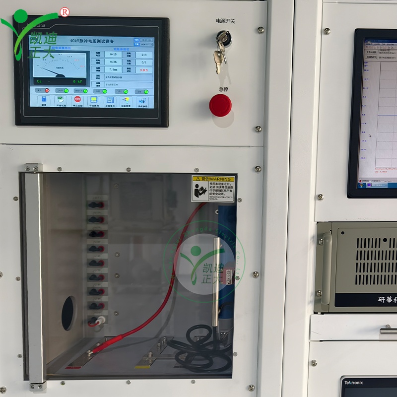
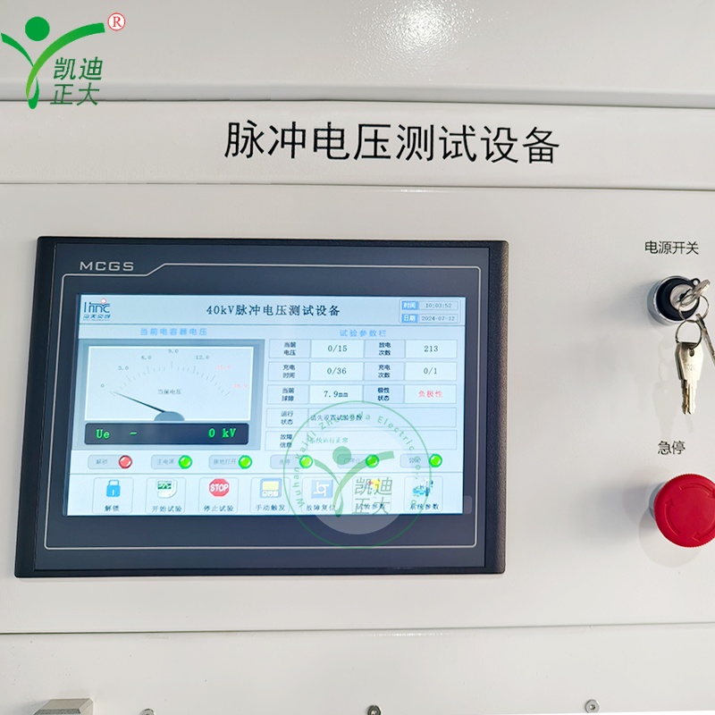
Complies with IEC61000-4-5 and GB18802.1-2012, used for combination wave (1.2/50μs voltage, 8/20μs current) tests of SPD, MOV valve plates and surge protectors. Applied in electrical labs and manufacturers for III-level certification and residual voltage verification.

  • Response within
    24 hours

  • Free warranty
    12 month

  • On-line training
    Support

Profile:

KDCW-20 is an automatic combined wave test system with PLC and computer control. It features dual waveform output, automatic polarity switching and 100MHz sampling, ensuring accurate and reliable surge protector performance testing.

Features:

  • Generates standard combination wave: 1.2±30%/50±10%μs voltage, 8±10%/20±10%μs current (no decoupling load)
  • Automatic positive/negative polarity switching, with separate setting of impulse times for each polarity
  • PLC + 10-inch touchscreen control, supporting automatic/manual trigger and parameter preset
  • 100MHz oscilloscope + dedicated software for waveform analysis, data storage and report generation
  • Built-in decoupling capacitor/inductor and 5-500V/5A action load power supply
  • Comprehensive safety interlocks: emergency stop, door limit switch, high-voltage grounding and overcurrent protection
  • Mobile cabinet with casters for easy on-site positioning and installation

Parameter:

  • Core Output Performance
    • Charging voltage: DC 0.5~25kV (max 22kV working voltage); Charging current: 0.1A
    • Charging time: 40~60s (at 22kV); Output impedance: 2Ω±10%
    • Voltage waveform (open circuit): T1=1.2±30%μs, T2=50±10%μs
    • Current waveform (short circuit): T1=8±10%μs, T2=20±10%μs (no decoupling load); T1=8±20%μs, T2=20±20%μs (with decoupling load)
  • Test Settings
    • Impulse times: 1~99 times (separate for positive/negative polarity); Interval time: 10~600s
    • Synchronization phase: 0~359° adjustable (accuracy ±5%); Residual voltage: ≤2.5kV
  • Power & Environment
    • Power supply: AC220V, 3kVA, 50/60Hz; Waveform distortion: <5%; Voltage fluctuation: <10%
    • Working temperature: -5℃~+40℃; Relative humidity: ≤85% (20℃, no condensation)
    • Altitude: ≤1000m; Ground resistance: ≤0.5Ω
  • Measurement & Control
    • Measurement system: TBS2102 oscilloscope (100MHz sampling, 20M storage), PINTECH N1030B differential probe (3kV), KDICM-20 Rogowski coil (20kA)
    • Control interface: 10-inch touchscreen, industrial computer with dedicated analysis software
  • Physical & Safety
    • Cabinet dimensions: 600×800×1800mm; Test chamber dimensions: 400×400×300mm (customizable)
    • Weight: ~600kg; Safety functions: High-voltage indicator, emergency stop, door interlock, manual grounding rod
  • Accessories
    • Standard accessories: Combined wave generator, oscilloscope, differential probe, Rogowski coil, decoupling module, action load power supply, user manual, calibration report