02 Aug-2024
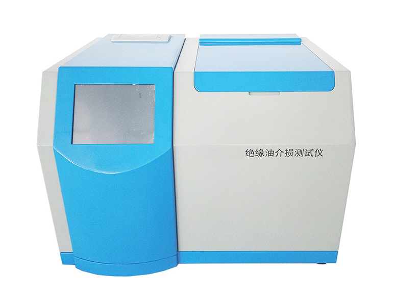
The insulation oil dielectric loss tester is a high-precision instrument used for measuring the dielectric loss angle and volume resistivity of liquid insulation media such as insulation oil. Integrated structure. Internally integrated with main components such as dielectric loss oil cup, temperature controller, temperature sensor, dielectric loss testing bridge, AC test power supply, standard capacitor, high resistance meter, DC high voltage source, etc.
The heating part adopts the most advanced high-frequency induction heating method currently available, which has the advantages of non-contact heating between the oil cup and the heating element, uniform heating, fast speed, and convenient control. The AC test power supply adopts AC-DC-AC conversion method, effectively avoiding the influence of mains voltage and frequency fluctuations on the accuracy of dielectric loss testing. Even if the generator generates electricity, the instrument can operate correctly. The internal standard capacitor is an SF6 gas filled three pole capacitor, whose dielectric loss and capacitance are not affected by environmental temperature, humidity, etc., ensuring that the insulation oil dielectric loss tester maintains consistent accuracy after long-term use.
Working principle of insulation oil dielectric loss tester
Heating up
The insulation oil dielectric loss tester uses a high-frequency induction furnace for heating, and after starting the heating, the temperature control CPU issues a heating command. At the same time, the temperature value of the internal temperature sensor of the oil cup is collected, and the heating is controlled by a combination of variable power control and PWM control. Using high-power heating method when the oil sample temperature is low is beneficial for shortening the heating time of the oil sample; When the temperature approaches the preset temperature, using a low-power PWM heating method is beneficial for uniform heating of the oil sample.
High frequency induction furnace heating avoids the phenomenon of uneven heating of heating blocks.
Temperature control
When the measured temperature approaches the preset temperature, the temperature control CPU of the insulation oil dielectric loss tester uses low-power PWM heating. The sampled temperature values are analyzed through PID calculation to determine the optimal PWM control duty cycle, ensuring that the temperature is strictly controlled within the preset temperature error range.
Dielectric loss measurement
The test voltage is simultaneously applied to the standard capacitor and the pressure electrode of the oil cup inside the instrument. The measurement circuit controls the PGA and other signals of these two channels, and synchronously samples the two channel signals through AD sampling. The digital signals are sent to the DSP (Digital Signal Processor), which performs filtering, FFT and other operations to calculate parameters such as tg, Cx, c, and sends them to the main control CPU.
Volume resistivity measurement
The DC high voltage test voltage is applied to the pressure electrode of the oil cup, and through the testing circuit, a weak current signal is generated. The weak current signal is amplified by the measurement circuit and sent to the AD sampling. The digital signal is sent to the DSP (Digital Signal Processor), which processes the signal, calculates parameters such as Rx and p, and sends it to the main control CPU.

