01 Aug-2024
The "harmonic superposition" testing unit of the relay protection tester can achieve the superposition output of various harmonic components of three-phase voltage and current, and is used to test the working behavior of power system equipment under various harmonic conditions. Commonly used to verify the differential harmonic braking coefficient.
UA, UB, UC, IA, IB, and IC can all stack DC and 2-20th harmonic outputs.
Each component can be displayed and recorded based on amplitude, or as a percentage of the fundamental wave.
You can choose to change automatically or manually, with both amplitude and phase adjustable.
Measurable action value, return value, action time, and return time.
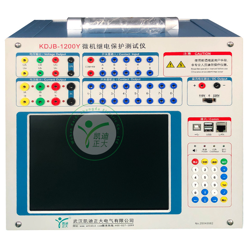
Interface Description
There are two display modes for harmonics in this module of the relay protection tester: one is in the form of amplitude, and the other is in the form of a percentage of the fundamental wave. At this point, the amplitude of the harmonic is directly related to the amplitude of the fundamental wave. Moreover, the superimposed waveform output by the tester is also related to the amplitude of this fundamental wave. Generally speaking, when conducting harmonic braking tests, the amplitude of the fundamental wave should be set to be greater than the set value of the protection (such as the starting value of differential protection) to ensure reliable protection when the harmonic is small or zero.
Set the amplitude and phase of harmonics on the relay protection tester page. The red data phase on the left refers to the channel of the corresponding phase where harmonics will be superimposed. There are two ways to represent amplitude, which is expressed in terms of amplitude. Therefore, its unit is the unit of current and voltage corresponding to it. If it is expressed as a percentage of the fundamental wave, it displays the percentage of the fundamental wave. The phase of the fundamental and harmonic waves here does not have a significant impact on the experimental results, so the default settings are generally sufficient. If it needs to be set, simply set the phase between the two according to the protection setting.
Data Reset Button: The test data set before the experiment may have changes in amplitude and phase during the experiment. After the experiment is completed, pressing this button can reset the data to its pre experiment state. This greatly facilitates repetitive experiments.
Refresh button: This button does not apply to parameters that have participated in the previous experiment, but only to new data modified before the next experiment. Can 'refresh' newly modified data to its original state before modification.
Reset button: It resets the amplitude of each waveform (including fundamental, DC, and 2-20 harmonics) displayed in the current window, and returns the phase to its default state. The phase of phase A returns to "0 °", the phase of phase B returns to "-120 °", and the phase of phase C returns to "120 °". This key is only valid for the parameters displayed on the current interface.
This is the display of the superimposed waveform. The relay protection tester can choose to display all three phases or display the waveform of one phase separately. What is displayed is the waveform of the A-phase voltage superimposed with harmonics. This graphic display is easy to compare with the oscilloscope's graphics.
The DC output range of each phase voltage is -160~160V, and the output range of fundamental and harmonic waves is 0~120V; The DC output range of each phase current is -10-10A, and the output range of fundamental and harmonic waves is 0-40A.
The sum of effective values of waveforms stacked in the same channel cannot exceed 120V (40A/30A). If it exceeds the range, the software will give an out of range prompt. At this time, please check the input value or whether the total amplitude after the data change has exceeded 120V (40A/30A). Overlay amplitude checks must be performed during both data input and output changes.