02 Aug-2024
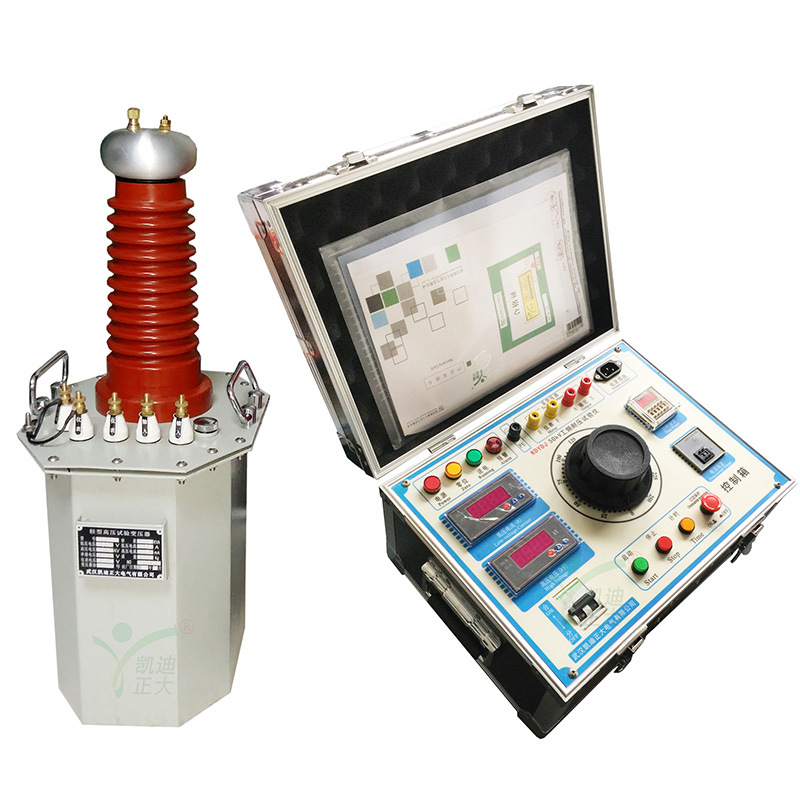
The power frequency withstand voltage test device consists of a power frequency test transformer and a withstand voltage control box. It is used to conduct insulation strength tests on various electrical products, electrical components, insulation materials, etc. under specified voltages to assess the insulation level of the products, discover insulation defects of the tested products, and measure the ability to withstand overvoltage.
1. Before the experiment, follow the wiring diagram of the power frequency withstand voltage test device instruction manual and pay attention to reliable grounding.
2. Before connecting the power supply, the voltage regulator of the operation box (platform) must be adjusted to zero first. After the power is turned on, the green indicator light will turn on. Press the start button, and the red indicator light will turn on, indicating that the transformer has been powered on and is waiting for boosting.
3. Rotate the voltage regulator handle clockwise at a speed of 1.5-2KV/S to increase the voltage, and pay close attention to the instrument indication and the condition of the test object. When the leakage current is too large or the test object is broken down, the overcurrent protection relay will quickly cut off the power supply.
4. After the experiment is completed, the voltage regulator should be adjusted to zero at a constant speed.
4. If it is found during the experiment that the pointer of the voltmeter swings greatly, the reading of the ammeter increases sharply, or the tested object emits smoke, arcs, has a focus position, and makes abnormal noises, the voltage should be immediately reduced, the power should be cut off, and the cause should be checked.
6. When conducting a DC test, the silicon stack short-circuit rod (D) and the series excitation tap terminal rod (C) in the high-voltage bushing must be loosened and pulled out, and wrapped with clean insulating paper. After completing the DC test and conducting the AC voltage test, two short-circuit rods must be screwed in.
7. During DC testing, current limiting resistors and filtering capacitors should be added to prevent damage to the silicon stack. After the experiment is completed, discharge with a discharge rod.
8. Environment; When the temperature is too high, a small amount of oil may overflow from the top of the casing, which is a normal phenomenon. When conducting a DC test, if there is obvious corona discharge on the inner wall of the sleeve, it is generally due to insufficient oil. At this time, the short-circuit rod should be removed and qualified 25 # transformer oil should be injected from its hole with a syringe.
9. When using the test transformer in series, it is necessary to pay attention to the corresponding connection between the output terminals (A) and (X) of the operation box and the output terminals (a) and (x) of the first test transformer. In addition to the corresponding connection between the output terminals (A, X) of the first test transformer and the input terminals (a) and (x) of the test transformer on the second JT1, its shell should be connected to the input of the primary transformer. The input terminals (a) and (x) of the test transformer on the third JT2 should be connected to the top output terminals (A) and (X) of the test transformer bushing on the second JT1.

