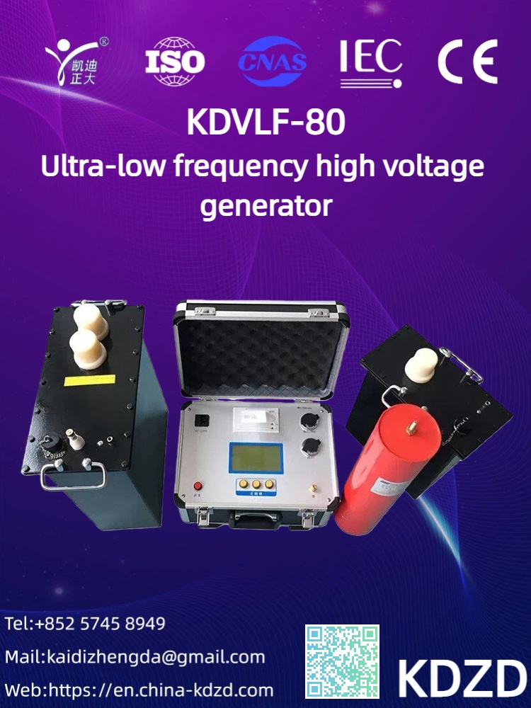

In power systems, high-voltage cables stretching for kilometers—or even tens of kilometers—act as the "arteries" of a city, buried underground or running through tunnels. Ensuring the health of the insulation in these "arteries" is critical. Once a fault occurs, locating and repairing it is extremely difficult and costly. The optimal tool for this preventive testing is the Very Low Frequency (VLF) High Voltage Generator.
So, why "Very Low Frequency"? And how does it solve the challenge of testing long-distance cables?
In the past, DC high voltage was commonly used for cable withstand tests. However, this method was found to have significant drawbacks:
Space Charge Effect: A DC electric field can cause a buildup of "space charges" within the cable insulation (such as cross-linked polyethylene, XLPE). These charges act like hidden "stress concentrators." Not only can they accelerate the aging of the insulation material, but even after the test, when the cable is re-energized with AC power, they can trigger unexpected insulation breakdown, effectively shortening the cable's lifespan.
Ineffective Simulation of Operating Conditions: Cables normally operate under 50/60 Hz alternating current. The electric field distribution in a DC test is entirely different from that of AC. Just as a static test cannot accurately reflect a dynamic athlete's performance, a DC test cannot reliably detect defects that only manifest under AC voltage.
To overcome the drawbacks of DC testing while avoiding the impracticality of on-site power-frequency AC testing (which requires massive, heavy equipment), engineers found an ideal compromise: Very Low Frequency technology.
"VLF" typically refers to frequencies of 0.1 Hz and below. Its advantages are key:
Equivalency: From an insulation testing perspective, the electric field distribution created by a 0.1 Hz VLF voltage within the insulation dielectric is nearly identical to that of a 50 Hz power-frequency voltage. This means a VLF test accurately simulates real operating conditions, effectively uncovering insulation weaknesses (like water trees, voids, etc.) that would only appear under AC stress.
Solves the Weight Problem: The current in a capacitive load is proportional to the frequency (I = ωCU). For a large capacitive load like a long cable, providing the huge current required at 50Hz results in enormous test transformers. Reducing the frequency to 0.1 Hz theoretically reduces the required current and power to 1/500th of the power-frequency requirement. This makes the test equipment compact, lightweight, and highly portable, perfectly suited for field applications.
This is the core strength of VLF technology:
The Capacitive Reactance Advantage: A cable is essentially a large cylindrical capacitor. Its capacitive reactance (Xc = 1 / 2πfC) is inversely proportional to the frequency. The lower the frequency, the higher the reactance.
Drastic Current Reduction: At high voltage, the charging current (capacitive current) flowing through the cable is the main burden on the test source. According to the formula, dropping the frequency from 50 Hz to 0.1 Hz reduces this capacitive current by a factor of 500.
Practical Impact: For a long cable with a fixed capacitance, the VLF tester only needs to supply a very small current to charge it to the required test voltage. This allows a relatively compact VLF generator to easily perform withstand tests on cables several kilometers long—a task that is nearly impossible at power frequency.
In summary, the VLF High Voltage Generator has become the gold standard for long-distance cable testing because it masterfully combines the real-world accuracy of AC testing with the field-portability of DC testing. It can precisely "interrogate" the cable's insulation for potential weaknesses, just like AC power, while its very low frequency drastically reduces the equipment burden. This allows engineers to easily bring a "high-voltage laboratory" to any remote site, performing a safe, accurate, and efficient "health check-up" on the critical arteries of our power grid.